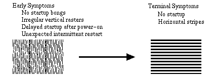
Diagnosis and Background
On startup, Power-ON reset signals are generated endlessly.
Solutions
First of all, please try solutions (1), (2) and (3). It is easy.
(1) Check and clean connections between SIMMs (ROM-SIMM) and SIMM (ROM-SIMM) slots, and restart.
(2) Remove PDS card(s) such as an accelerator card if installed, and restart.
(3) Check the battery. Replace it with a new one if voltage is low, and restart.
If nothing above works, try solutions (4), (5) or (6) AT YOUR OWN RISK. You NEED soldering and desoldering skill.
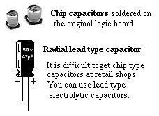 (4) Replace electrolytic capacitors C6 (1µF 50V) and C7 (47µF
16V) on the logic board with new ones. Surface mount chip type
capacitors are soldered on the original logic board. But you can use
miniature radial lead type capacitors instead.
(4) Replace electrolytic capacitors C6 (1µF 50V) and C7 (47µF
16V) on the logic board with new ones. Surface mount chip type
capacitors are soldered on the original logic board. But you can use
miniature radial lead type capacitors instead.Anyway, be carefull about desoldering and soldering procedures not to break circuit patterns on the board. Make sure the polarity of electrolytic capacitors before soldering.
If you find liquid leak or corrosion of other capacitors, it is a good idea to replace them or all electrolytic capacitors with new ones. Macintosh SE/30 was introduced in 1989 and discotinued in 1991. Electrolytic capacitors have been degraded after years.
(5) If solution (4) doesn't work, pull up the sound IC chip
(UB11). You can see letters "SONY 0F09G 3430045B APPLE85" or "SONY 9A04
3430045B APPLE85" printed on the chip. To pull up the IC chip, connect
pin 7 to pin 15 of the chip with a 1 kilo ohm resistor.
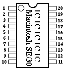
Numbering of IC Pins:
IC pins are numbered counterclockwise. Pin 1 is located at the corner marked by a small circle or dot on the chip.
(6) If solution (5) doesn't work either, replace the network filter RP2 (Bourns 4120R-601-250/201).
Also see 9. Bright Monitor with neither Arrow Pointer nor Startup
Replacement of chip type electrolytic capacitors solves the SimasiMac problem in most cases.
Even if you don't have capacitor-related troubles, it's a good idea to replace them.
C1, C3, C4, C5, C7, C8, C9, C10, C12, C13: 47µF 16V
C6: 1µF 50V
2. A Bright Vertical Line in the Black Monitor
 Symptoms
When starting up Mac SE/30, only a bright vertical line is shown in the
black monitor. The width of the vertical line is approximately 5 mm.
During start-up, you can see moving raster patterns in the vertical
line. You can hear spinning sound of the hard disk drive also. The hard
drive seems to be OK, and the vertical line seems to show the startup
picture though very compressed to 5mm in width.
Diagnosis
The horizontal sweep circuit on the analog board is broken.
Ageing
and/or cracks in the soldering of either (1) P1 connector, (2) C15
electrolytic capacitor (3.9uF, 35V, 85degree C, HighFrequency,
NonPolar) or (3) L2 variable inductor on the analog board is the major
cause of the problem.
The most frequent cause is soldering failure of the P1 connector due to
ageing and/or cracks. In this case, you will see the burnt and/or
charred P1 connector.
Solutions
The first thing to do is to check the connector, capacitor or the
inductor, and then desolder, clean and resolder them. If the problem
still persists, replace the parts with new ones.
3. A Fine Vertical Line in the Black Monitor
 The First Thing To Do Is To Turn Off The Power!!!!!!!!!!!
Symptoms
Mac SE/30 shows a fine vertical line in the black monitor. In addition,
you may be able to see and/or smell smoke coming up from the SE/30.
It's burning. Shut off the SE/30 immediately, and pull out the power
plug.
Diagnosis
The horizontal sweep circuit on the analog board is broken.
The R19 resistor (220 ohm, 1/4W, 5%) on the analog board is burnt out.
Solutions
Check the R19. If it is burnt, cracked and/or charred, replace it with a new one.
4. Herringbone Pattern Regardless of Startup
 Symptoms
When turning on the SE/30, the monitor is wavy and shows herringbone rasters.
Sometimes with startup bong and smile Mac, sometimes without startup bong nor smile Mac.
Diagnosis
One cause is a trouble of the flyback transformer on the analog board
at reference T2. The T2 flyback transformer is shielded by a metal
cage, and a cable with an anode cap is attached on its top.
For SE/30, three versions of the flyback transformer were used as listed below.
157-0042A
157-0042B
157-0042C
You can identify the version/parts number by the label attached on the side of the flyback.
This trouble has been found most frequently in the early lots of SE/30,
in which the 157-0042A flyback was installed. The later lots of SE/30
even with the 157-0042B or 157-0042C version also can show the same
trouble because of ageing and degradation of the flyback transformer.
Solutions
Replace the flyback transformer with new one. Don't use 157-0042A. Use 157-0042B or 157-0042C.
Even if the flyback you can get is a used one, check its version.
5. Monitor Black Out with/without Startup
 Symptoms
As to the symptoms when turning on the power, there are four types including
(1) Black monitor with startup bong;
(2) Black monitor with startup bong and with spining sound of fan and hard disk drive;
(3) Black monitor without startup bong but with click noise; and
(4) Black monitor without startup bong and without click noise.
Diagnosis
The most probable cause of this trouble is damage of the CR2/CR3 rectifiers or the Q2 transistor.
Troubles of the T2 flyback transformer sometimes results in this problem.
The broken CR5 rectifier also causes these symptoms, though rarely.
CR2
and Q2 are placed on the outer surface of the metal cage, which shields
the flyback transformer on the analog board. The cage metal around CR2
and Q2 is locally discolored/charred, or these parts are exploded by
high temperature.
If the CR3 rectifier is damaged by heat, explosion of CR3 usually
occurs. CR3 is placed on the inner surface of the shielding metal cage.
When CR3 is damaged but not exploded, the Q2 transistor may be damaged
simultaneously. In this case, Q2 is sometimes burnt and sometimes is
not.
When Q2 is burnt out but CR3 seems to be OK, the CR5 rectifier is probably damaged.
Even if all CR2, CR3, CR5 and Q2 appear to be OK, the inner circuits of these parts are sometimes destroyed by heat.
Even if all these semiconductors are OK, destruction of the R22
resistor also can cause Symptom(2) as described above (Black monitor
with startup bong and with spining sound...).
Solutions
Replace the broken semiconductor or resistor with new one.
CR2 and CR3 (silicon rectifying diode): GI854 (600V,3A). The much better is MR824 (600V, 5A).
CR5 (silicon rectifying diode): 1N4937 (600V, 1A).
Q2 (NPN transistor): BU406 or BU406D (7A, 60W). If you cannot get BU406/BU406D, use RCA SK9085.
R22 (resistor): 470 Kohm, 1/2 W, 5%.
When the SE/30 appears totally dead (black out monitor, no startup
bong, no spinning sound, no noise), the major cause of the problems is
the power supply (SONY or ASTEC). Check the power supply/power switch
with a digital multimeter. If the power supply doesn't work, replace it
with another one (new or used).
6. A Bright Horizontal Line in the Black Monitor
 Symptoms
(1) The SE/30 starts up and works normaly. After a while, the monitor suddenly blacks out only with a bright horizontal line.
OR
(2) When turning on the SE/30, you can hear the startup bong but see only a bright hrizontal line in the black monitor.
Diagnosis
The vertical sweep circuit on the analog board doesn't work.
The major cause of this trouble is either of (1) connection failure due
to ageing and/or cracks in the soldering of the P1 connector, or (2)
troubles of the vertical sweep IC chip at reference U2 (12-pin TV,
TDA1170A) on the analog board.
Solutions
(1) The first thing to do is to check the P1 connector. If the problem
is caused by connection/soldering failure of the P1 connector, you will
see the burnt and/or charred P1 connector. Desolder, clean and resolder
the P1 connector.
(2) If the problem still persists and the culprit is the U2 IC chip, replace it with a new TDA1170N chip.
When the U2 IC chip is broken, you may see another symptoms such as:
(1) The screen is shrunken to the upper/lower half of the monitor and the opposite half blacks out,
(2) The upper/lower half of the screen is extended in the vertical direction.
7. Checker Flag Pattern
 Symptoms
When turning on the power, you don't hear startup bong. The monitor displays the checker flag pattern.
Diagnosis
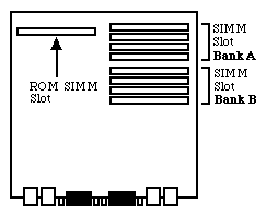
(1) The most probable cause is connection troubles between the ROM-SIMM and the ROM-SIMM slot.
(2) Another cause is inappropriate installation of RAM-SIMMs. The
memory size of RAM-SIMMs in Bank A is smaller than that in Bank B. You
recently upgraded the memory but the configuration was wrong.
 Solutions
(1) Pull out the ROM-SIMM from the ROM-SIMM slot. Clean the ROM-SIMM
and the ROM-SIMM slot with volatile cleaner or ethanol. Then connect
the ROM-SIMM to the ROM-SIMM slot correctly and tightly.
(2) See "Principles of memory upgrade for the SE/30" in the next section, 8. Jail Bar Pattern or Smile Mac in Jail.
When you install SIMMs of different memory size, install the larger
ones to Bank A and the smaller ones to Bank B. Each Bank requires a set
of four SIMMs of the same memory amount.
8. Jail Bar Pattern or Smile Mac in Jail
 ¡¡OR¡¡
Symptoms
When you turn on the SE/30, the monitor displays vertical stripes (jail
bar pattern) with/without a smile Mac. The memory was upgraded
recently. The SE/30 was completely nomal before memory upgrade.
Diagnosis
SIMMs were inserted to the wrong SIMM slots/banks.
Solutions
The working memory configurations for the SE/30 are shown in the table below.
Check and re-insert the SIMMs.
Note 1
The SE/30 has eight RAM-SIMM slots on the logic board: Four slots at Bank A and four slots at Bank B.
Principles of memory upgrade for the SE/30:
(1) Use 30-pin SIMMs.
(2) You need to install a set of four SIMMs of the same memory size to each bank.
(3) When you use only a single bank, use Bank A.
(4) When you install SIMMs of different memory size, install the larger
ones to Bank A and the smaller ones to Bank B. You also have to
remember that each Bank requires a set of four SIMMs of the same memory
amount.
(5) It has been reported that some 2MB SIMMs and some 16MB SIMMs don't work for the SE/30.
Note 2
The SE/30 has a "dirty ROM" that can recognize only 8MB RAM, and the
maximum RAM for the SE/30 is 8MB under the normal condition.
But if you install the MODE32 extension file, the SE/30 can recognize up to 128MB RAM.
You can download the MODE32 extension file (click here) from the Apple download site.

| Total Memory | Bank A | Bank B |
| 1MB | 256KB x 4 | Empty |
| 2MB | 256KB x 4 | 256KB x 4 |
| 4MB | 1MB x 4 | Empty |
| 5MB | 1MB x 4 | 256KB x 4 |
| 8MB | 1MB x 4 | 1MB x 4 |
| 12MB | 2MB x 4 | 1MB x 4 |
| 16MB | 2MB x 4 | 2MB x 4 |
| 16MB | 4MB x 4 | Empty |
| 17MB | 4MB x 4 | 256KB x 4 |
| 20MB | 4MB x 4 | 1MB x 4 |
| 24MB | 4MB x 4 | 2MB x 4 |
| 32MB | 4MB x 4 | 4MB x 4 |
| 64MB | 16MB x 4 | Empty (No Good) |
| 68MB | 16MB x 4 | 1MB x 4 |
| 72MB | 16MB x 4 | 2MB x 4 |
| 80MB | 16MB x 4 | 4MB x 4 |
| 128MB | 16MB x 4 | 16MB x 4 |
9. Bright Monitor with neither Arrow Pointer nor Startup
 Symptoms
When turning on the power, you can see bright rasters on the monitor, but neither startup bongs nor arrow pointer comes up.
Diagnosis
The culprit is the network filter located on the logic board at reference RP2.
The model of the chip is Bourns 4120R-601-250/201, M/C 8908L 115-0002
or P9120M115-0006, depending on the lot, year and/or country where the
logic board was made.
Solutions
 (1)Replace the network filter.
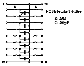
(2)This network filter chip, however, is hard to find/obtain at resale
parts shops. If you have a skill to make it yourself, refer the circuit
schematic of the filter as shown in the left figure. It is made of
sixteen 25 ohm resistors and eight 200pF capacitors. Assemble and
solder them on a small IC socket, and then solder this socket on the
logic board at reference RP2.
You can download the data sheet of Bourns 4120R-601-250/201 at the Bourns site.
10. An Arrow Pointer on the Left Upper Corner but No Smile Mac and No Startup
 Symptoms
When turning on the power of the SE/30, the monitor shows the bright
rasters and an arrow pointer appears on the left upper corner. But the
monitor doesn't show a smile Mac, and the SE/30 doesn't start up.
Diagnosis
The most probable cause is a trouble of the SCSI chip on the logic board at reference UI12.
This chip is labeled "NCR 53C80 CP02346 609-3400257 8907N" on the top.
Solutions
Replace the UI12 SCSI chip with new one (44-pin PLCC, 53C80-P44).
11. Monitor Out of Focus
 Symptoms
The monitor of the SE/30 is out of focus. Except that, everything is OK.
Diagnosis
The variable resistor at reference R27 on the analog board is not adjusted correctly.
Solutions
Open the SE/30 and look at the vinyl jacket of the analog board. You can see a hole labeled Focus Control.
Adjust the focus using a hex tool (or screw driver) put into the hole.
If you cannot get the best focus only with re-adjustment of R27,
replace the R26 (not R27) resistor with new one (1 Mohm, 1/2 W, 5%).
12. Too Bright Monitor with Horizontal Sweep Lines
 Symptoms
The SE/30 monitor is too bright, and you can see many horizontal sweep lines.
Even if you adjust the brightness control under the front bezel, the symptom is not improved.
Diagnosis
There are five known causes for this symptom.
(1) The R24 variable resistor on the analog board is not adjusted correctly. This resistor controls the cut-off voltage.
(2) Troubles of the resistors R20 and/or R21 on the analog board.
(3) Troubles of the resistor R25 on the analog board.
(4) Troubles of the IC chip U1 on the analog board.
(5) Troubles of the transistor Q1 on the video board. The video board is a small board where the CRT socket is soldered.
Solutions
(1) On the vinyl jacket of the analog board, you can see Focus Control,
Brightness Control, Width Control and Height Control for video
adjustments. Using the plastic hex alignment tool (screwdriver may be
OK, if you don't have the hex tool) put into the Brightness Control
hole, adjust the brightness so that the sweep lines disappear and the
monitor shows the best images.
(2) If the above solution doesn't work, replace either or both of the resistors R20 (100 Kohm, 1/2 W) and R21 (1 Mohm, 1/2 W).
(3) If solutions (1) and (2) don't work, replace the resistor R25 (470 Kohm, 1/4 W).
(4) If solutions (1), (2) and (3) don't work, replace the U1 IC chip (74LS38).
(5) If none of the above doesnt't work, replace the transistor Q1 (2N3904, NPN transistor) on the video board.
13. A Bright Pixel at the Center of the Black Monitor
 Symptoms
When you turn on the The SE/30, you can see only a bright pixel at the center of the black monitor.
This phenomenon appeared after disassembling and reassembling the SE/30.
Diagnosis
Both horizontal and vertical sweep circuits on the analog board don't work.
Althogh both circuits may be broken simultaneously, this possibility is very small.
This occurs most frequently when you disassemble and reassemble the
SE/30. The most probable cause is that the yoke cable does not connect
tightly to the P1 connector on the analog board.
Solutions
Disassemble the SE/30 again, and check the connection between the yoke cable/connector and the P1 connector.
14. Wavy Display, Swaying Back and Forth of the Image
 Symptoms
Normal startup and normal display. But for a short period, the display
is sometimes wavy, and the image is swaying back and forth (or small
and large) on the display. Then, the display becomes normal.
Diagnosis
The power supply is getting degraded and unstable with ageing. All
components of the SE/30 can be affected by unstability of the power
supply. The monitor is most vulnerable, because it requires very high
voltage. This symptom, in general, indicates fluctuation of voltage for
the monitor.
Solutions
Replace the power supply.
The power supply of the SE/30 (and SE) was made by SONY and ASTEC. The SONY power supply has less trouble than the ASTEC.
III. References
1. Books
- (1) Macintosh Repair & Upgrade Secrets.
- Larry Pina, Heyden Books, 1990.
- (2) The Dead Mac Scrolls.
- Larry Pina, Goldstein & Blair,1992.
- (3) Mac Classic & SE Repair and Upgrade Secrets.
- Larry Pina, Peachpit Press, 1993.
- (4) Macintosh II Repair and Upgrade Secrets.
- Larry Pina, Brady Publishing, 1993.
- (5) Build Your Own Macintosh and Save a Bundle., 2nd Ed.
- Bob Brant, Windcrest/McGraw-Hill, 1992.
- (6) Upgrading & Repairing Mac.
- Lisa Lee, Hayden Books,1995.
- (7) PC & Mac Handbook: Systems, Upgrades & Troubleshooting.
- Steve Heath, Butterworth-Heinemann, 1996.
- (8) Professional Macintosh Repair.
- David Presnell, Prompt Publications, 1996.
- (9) Guide to the Macintosh Family Hardware, 2nd Ed.
- Addison Wesley, 1990.
- (10) Troubleshooting and Repairing Computer Monitors, 2nd Ed.
- Stephen J. Bigelow, McGraw-Hill, 1996.
- (1) OPEN DESIGN No.2, Macintosh Interface and Networking (in Japanese).
- CQ Publishing, 1994.
- (1) Apple Service Source v2.0 CD-ROM.
- Apple, 1997.
- (1) se30ers mailing list (in Japanese).
- Maintained by Junichi Takeuchi, the president of The SE/30ers of Japan, Enthusiasts for Macintosh SE/30.
- (1) OldMac SIG Library in the Mac Users Forum of NiftyServe (in Japanese).
- (1) Other various technical documents.
IV. Where and How to Get Repair Parts
Listed in alphabetical order.
1. Parts and/or Used/Refurbished Macs
- Alltech Electronics
- Electronic Surplus Online
- GALAXY
- ICN (Innovative Computer & Networking)
- MacResQ
- Mac Sale International
- MacSensei
- MacVizion
- MacWorks
- MediaGuide
- MC Computers
- MP Computers
- NEXCOMP
- PowerBook1
- Power ON
- Shreve Systems
- Sun Remarketing
- Symmetry Computers
- Timco Computers
- Union Electronic Distributors
- Vintage Computer
- A & R Computing
- Eritech
- HBR Enterprises
- Memory Lane
- Memory Technologies Texas
- MicroExchange
- Source Computing
- eBay Computer, Search Keywords=(SE/30,SE30,SE-30)
- Google
Go to Google, and put "Macintosh parts" or "Mac parts" or anything you like for keywords.
You will find a lot of parts/used Mac stores on the Web.
V. Acknowledgment
Thanks All Mac/Computer Wizards, Gurus, Geeks, Nerds, Maniacs, Enthusiasts and Devoutees.Go to INDEX
Go to Full of Mac
 Repair Macintosh SE/30
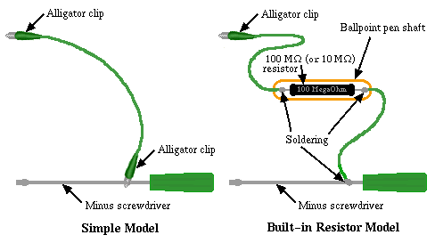
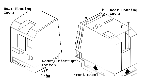 (1) Using a small screwdriver, pry off the reset/interrupt switch on the left side of the case.
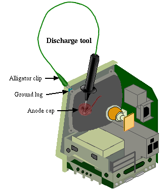 If you are working on a compact Mac that contains a CRT (just like
SE/30) and incorrectly discharge the CRT to the metal chassis, you may
destroy the logic board.