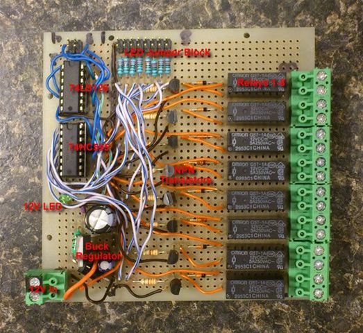
This is general purpose module that could be used for a dozen other projects. For my purpose it will be used to control the 12V solenoid water valves that will water each zone of my garden.
The power for our system comes from a 12V battery attached to our solar grid, so all our power will be based upon a 12V design. To this end I'm using Omron G5T-1A 12V SPST relays. Below are the schematics.
Buck Regulator Schematic
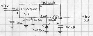
Power! Since we're running off a 12v battery, we need a way to provide 5v for our digital logic. In normal circumstances, I would use a linear voltage regulator such as a 7805, but those dump off their excess power as wasted heat... I'm not going to bother with the calculations here but linear regulators get more inefficient as the voltage input increases (In our case we'd be dumping 7v!) Instead we'll use a switching regulator. While more expensive, we're getting 75% effiency according to the datasheet if we were to draw the full 3A. This instead of about 20-40% with a 7805.
Relay and Arduino Logic Schematic
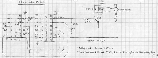
Okay... Maybe we should break this down into sections. Let's start with the 74LS126 and the 74HC595 and then move into the NPN/Relay portion.
74LS126 and 74HC595
These two components make up the interface from Arduino to the relays:
The 74HC595 is an 8-bit shift register. I can write a single byte to the device which in turn becomes present on the data pins (Q0-Q7, Q0 being the LSB (least significant bit)). In this way I can turn on multiple relays at once. For example if I wrote 255 which is FF in hex and 1111 1111 in binary I would turn on all 8 relays.
I write these bytes by connecting them to Arduino digital pins 1-3.
But... I've got a heck of a load of other stuff that I want to connect to my Arduino for this project. So I can't have one circuit hogging three pins! If only there was some way to disconnect them.
Enter the 75LS126. This is a tristate buffer. If I connect my 74HC595 pins through here and then to the Arduino I can effectively "unplug" them from the bus by toggling D0 LOW. If D0 is HIGH then I've reconnected them. This allows me to use D1-3 for other circuits.
So, I'm hogging 1 pin instead of 3. You could also use a 74LS125. This "unplugs" D1-3 when D0 is HIGH, so opposite to the 74LS126.
Arduino Pins
D0 = Tristate (74LS126)
D1 = Latch '595
D2 = Data '595
D3 = Clock '595
NPN/Relay
Digital logic runs at 5V, Solenoid valves run at 12V and can draw a lot of current. What to do...
So moving from lef to right. in the schematic. The first stage here is a LED to visually indicate which zones are active. Next we have a current limiting resistor connected to an NPN transistor.
Explanation: The 74HC595 can only output so much power from each of its data pins. The datasheet indicates that total Amperage cannot exceed 70mA total with each output pin a max of 35mA (or 25mA in the case of Q7). If I were to hook up the relays (which have a 16.7mA draw for their coil) directly to the 74HC595 and then proceed to turn on all zones, I would draw 133.6mA... Not to mention the power required to light up the LEDs (which is about 2mA per I believe).
I'm using a variety of small BJT transistors from my parts drawer. Some of them are probably close to 30 years old! Here's a list of what's being used on the board:
PN2222
TIS97
2N3904
2N5089
52 49A
The theory here is that most of these transistors have a gain of 50 on the base. That means that whatever current I allow to pass through will be 50x between the Collector and Emitter. Here's the calculation below:
So we have a 5v input to the transistor circuit. The transistor between collector and emitter bleeds off about 0.7v so we're left with 4.3v to work with. If I'm using a 3.3KOhm then according to Ohms law:
I = V/R
I = (5v - 0.7v) / 3300Ohms
I = 0.0013A or 1.3mA
So the current I'll have available between collector and emitter will be: 1.3mA * 50 = 65.15mA. Translation... Plenty more then is required for the 16mA required by the relay coil.
In the end that means off of each pin the 74HC595 will be drawing only 3.6mA (including the LED) or
28.8mA total with all relays active.
The diode is vital as part of this circuit. When an active relay is shut off, there is a momentary surge of current in the collector end of the circuit. The diode provides a way back for the current instead of blowing the transistor.
Circuit Testing
After carefully essembling each section I hooked the circuit up to an old PC ATX PSU. On the breadboard I assembled in the following order:
Buck regulator circuit (then tested), transistor section (then tested), relay section (then tested), LED block (tested), 74LS126 and 74HC595 (tested again). Sorry to harp on it for those of you whom have plenty of experience with this already...
Arduino Test Program
Of course we need to make sure this works with the Arduino. Here is a simple test program that counts from 1-255 thereby testing each relay in every combination. Tie your D0 input High if you're using a 74HC595 to make sure the D1-D3 lines are active.
  //Pin connected to ST_CP of 74HC595
int latchPin = 1;
  //Pin connected to SH_CP of 74HC595
int clockPin = 3;
  //Pin connected to DS of 74HC595
int dataPin = 2;


void setup() {
  //set pins to output so you can control the shift register
    pinMode(latchPin, OUTPUT);
    pinMode(clockPin, OUTPUT);
    pinMode(dataPin, OUTPUT);
}


void loop() {
    // count from 0 to 255 and display the number
    // on the LEDs
    for (int numberToDisplay = 0; numberToDisplay < 256; numberToDisplay++) {
       // take the latchPin low so
       // the LEDs don't change while you're sending in bits:
       digitalWrite(latchPin, LOW);
       // shift out the bits:
       shiftOut(dataPin, clockPin, MSBFIRST, numberToDisplay);


       //take the latch pin high so the LEDs will light up:
       digitalWrite(latchPin, HIGH);
       // pause before next value:
       delay(500);
    }
}
Documents
LM2575HVT-5.0 (PDF)
Omron Relay (PDF)
74HC595 (PDF)
PN2222 (PDF)
Links
Controlling a relay with a digital logic level (68k Friendly)
Last Updated: May 30, 2020