16x iPod Charger / Lockbox
Introduction
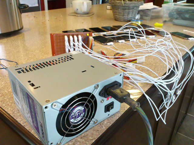
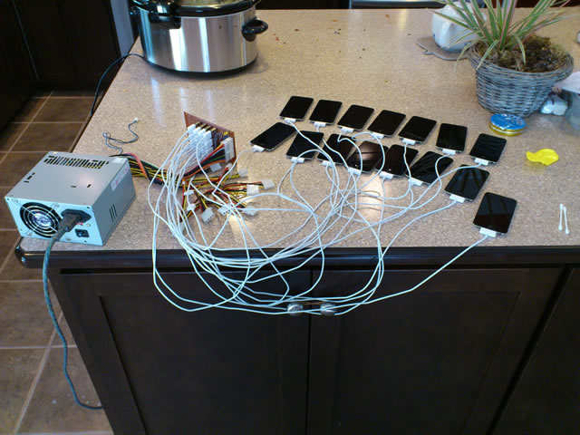
Our School bought 15 iPods for student use. We needed a way to charge all 15 and keep them secure. Online it looks like the going rate is about $1200 for charging/securing and $750 for just charging.
After seeing the Minty Boost reverse engineer video I thought... heck this can't be that difficult. And really it isn't... And so after about $200 we now have something that works pretty good.
First Things
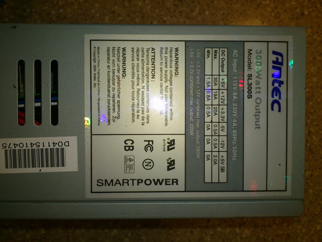
ATX power supplies found in every desktop computer are perfect for many power projects. They provide clean reliable power at 12, -12, 3.3 and 5 Volts in addition to some other stranger signals.
iPods or iPhones require 5V for charging at either 0.5 or 1 Amp. The way it determines whether to charge or not is by different voltages placed on the two USB data lines (D+ and D-). Without this newer iPods won't charge. This is accomplished by using resistors to drop voltage from either the 5V line or 3.3V to the levels required by the iPod.
Armed with this knowledge and a couple of simple formulae there is not much circuitry required to build a functional charger from an ATX PSU.
Tools/Parts Required
For this project you'll need:Sidecutters
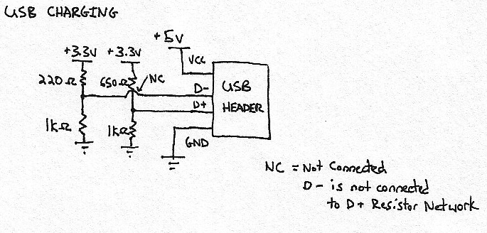
Below is the basic circuit for USB charging. Charging multiple USB devices simply means hooking up additional USB headers to the same circuit bearing in mind Amperage limitations on the 5V lines.
Needle Nose Plyers Wire Strippers
Soldering Iron
Heat Gun
Multimeter
Exacto Knife
Drill
Hole Saw
Phillips Screw Driver
1 Breadboard of a decent size
1 ATX PSU
1 ATX Female Header
16 USB A Vertical female headers (Jameco USB-A-S-VT)
2 1 KOhm resistor (1/8W)
1 220 Ohm resistor(1/8W)
1 680 Ohm resistor (1/8W)
1 Gun case with foam inserts
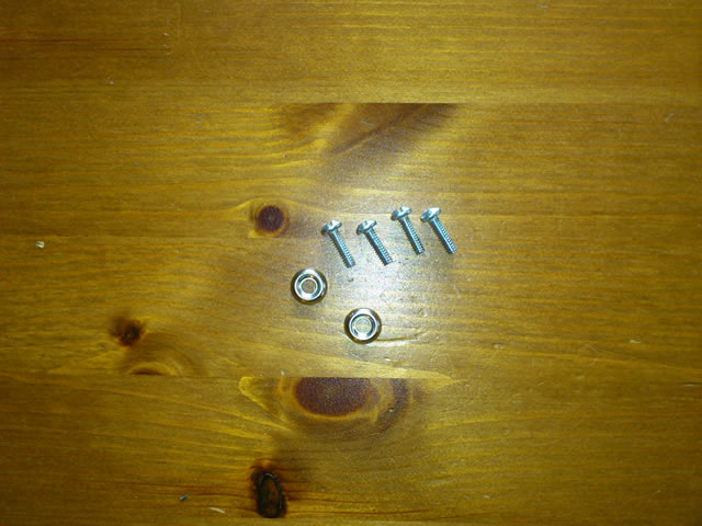
4 1-inch screws with washers
4 Motherboard standoff screws (pilfered from an old ATX PC case) and standard PC screws
4 Fan screws from ATX case
1 Fan grate from ATX
Rosin Core Solder (you'll need quite a bit)
18AWG Wire (pilfered from another ATX PSU)
Some Math
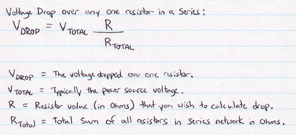
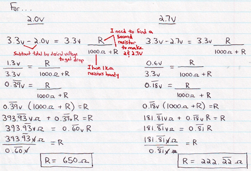
To get the voltage required on both USB data pins we need to implement a voltage dropping circuit. The signal we need is only voltage, no current will flow to the data pins. Therefore the entire load will be drawn across the resistor networks.
I will be drawing 1A at 5V for each iPod so according to various sources on the internet I will need between 2.7V and 2.8V on D- and 2.0V on D+.
Since the iPods will be using the 5V lines for charging I decided to use the 3.3V lines for the D+ and D- signals.
Below are the equations required to isolate the correct resistors needed...
I started with two 1 KOhm resistors to make my math easier (they're also what I had on hand). In the end I was able to find a 220 Ohm and a 680 Ohm resistor which were close enough in value to what I needed to get the voltage levels right.
The Basic Circuit
Since I'm designing the charger to juice 16 devices simultaneously at 1 Amp each I need to consider the PSU and the stress the current will put on the wires and circuit board.
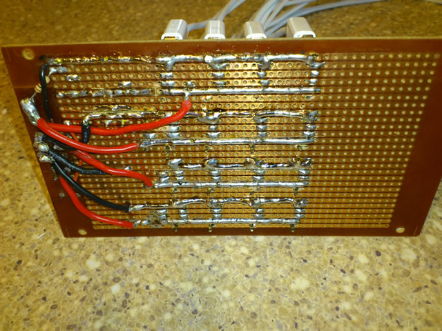
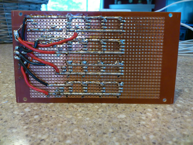
The PSU uses 18AWG wire for its ATX header and there are four red 5V cables. I can distribute the load by placing four USB headers on each wire for a total of 4A drawn at max load on each. According to my reading 18AWG can take a max load of 16A for chassis wiring and 2.3A for power transmission so I'm pretty sure I'm okay. On the circuit board I fortified the 5V and GND traces with extra solder to beef up their power transmission capabilities.
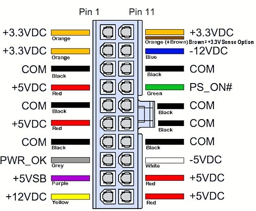
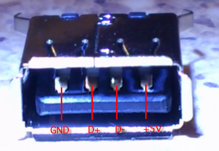
Pinouts
20 Pin ATX Connector 4 Pin USB-A Female Header
Assembly
Circuit Board
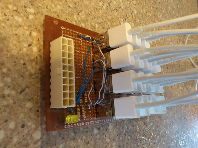
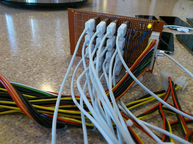
To obtain a ATX header I used a heat gun to remove mine from an old ATX motherboard. For my prototype (As seen in the picture above) I also removed one of the dual USB headers.
I clipped the extraneous pins on the ATX header (everything that wasn't 5V, 3.3V, Green Power, and GND) and then drilled out my breadboard to accomodate the header.
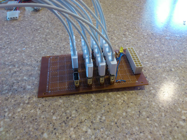
After doing so I shorted the Green Power line to GND so that when the PSU is plugged into the board it is turned on. I then wired up an LED to indicate power status.
From there it is a simple matter of putting the resistor network in place and wiring up the rest of the circuit according to the schematic above. To the right is my terrible job soldering up the USB headers. As you might be able to infer the shell of the USB header is grounded along with the GND line on the header.
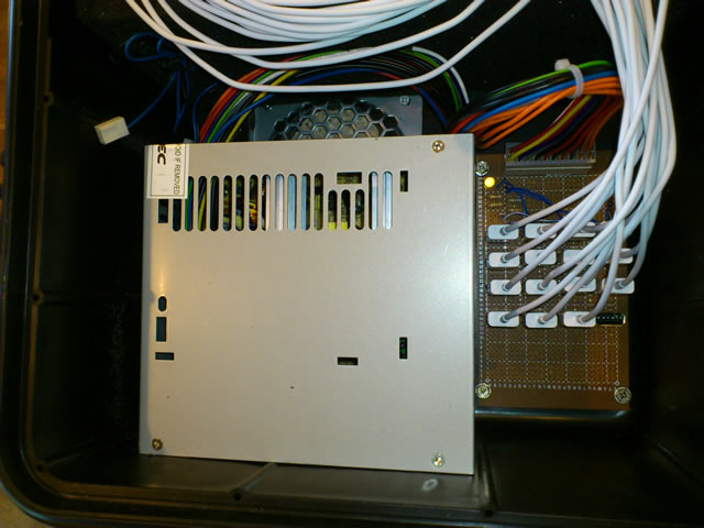
In order to mount the breadboard in the box I used motherboard standoff screws from an old PC. After drilling small holes I was able to screw them down and mount the board neatly beside the ATX Power Supply.
As for the ATX PSU I clipped off the extraneous power headers to save room in the case and allow for better air circulation.
Case
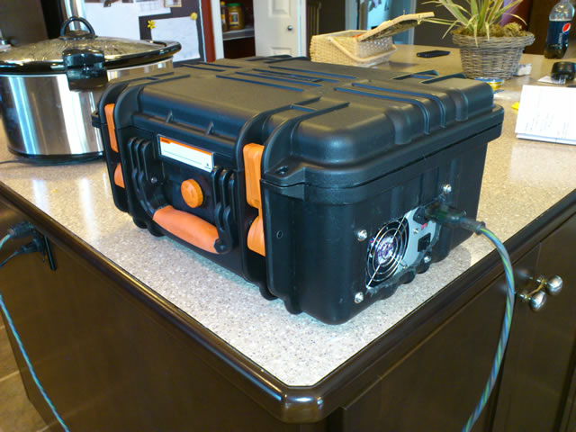
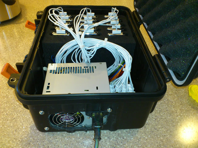
Our VP purchased a gun box measuring about 12" by 16" containing removable foam inserts. After cutting the foam in half it allowed room for the ATX PSU, breadboard and USB cables. The rest of the foam was divided into two layers of hexagonal pipes. After removing the appropriate foam I was left with room for 3 rows of 5 iPods.
Our VP took the case home and drilled out the bottom of the case for a vent and covered it with a fan grate from an old PC. Additionally he cut out the outline of the ATX PSU on one side and mounted it with 1" screws with washers.
As mentioned before I mounted the breadboard and kept the USB cables tied up nicely with white tie wraps. To secure it we purchased two heavy duty padlocks to keep them safe. Below are some pictures of the final product.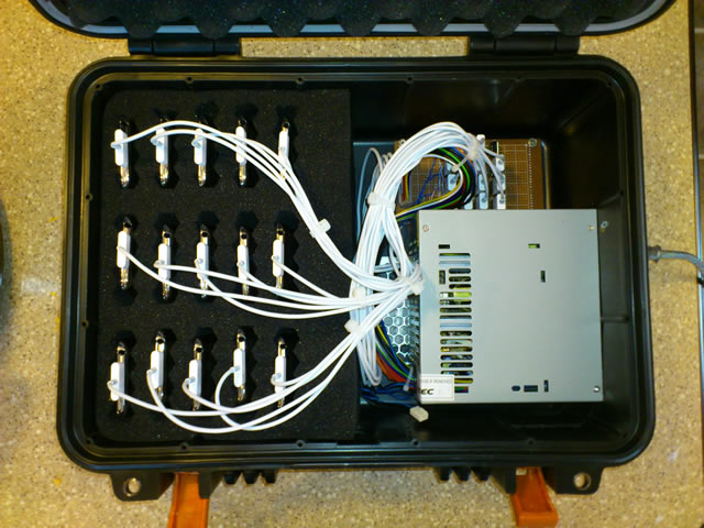
Links
Wire Gauge and Current Limits
All About Circuits: Voltage Divider Circuits