The HeidiBot
History
After I built the Stubot my daughter became jealous so I promised I would build her a robot too. I also wanted to address a number of the shortfalls of the Stubot.1. The charge control circuit was largely unnecessary as it's cheap to purchase a 8.4V adapter online.
2. I designed the circuit with little thought to the overall design so the Stubot is a bit of a mess. This robot will have style.
3. I didn't design the bot to be easy to take apart or modify.
4. I wanted to play with some new sensors.
5. The rig I had to set up to program the darn thing was super sketchy and doesn't work half the time because I forget to connect a wire.
Final Specifications
- 1 Ultrasonic sensor (to detect the distance from objects).
- 1 Light sensor (to detect ambient light level to switch on LEDs when it gets dark.)
- 1 voltage sensing circuit (to detect the battery levels)
- 2 geared motors and H-Bridge module (for drive and steering)
- 1 On/Off Push button
- 2 Bi-colour LEDs
- Voltage regulating circuit (to provide correct 5V voltage for Arduino and sensors).
- 2 Lithium Ion rechargable batteries (connected in parallel for 8.4V output max).
Looking for Parts
I actually did a lot of the purchasing this time from eBay to make the build easier. I did use some recycled materials however
Coil Old VCR (2 50uH in series) LED Holders From another abandoned project Wood Chassis The kids old crib Hookup Wire Cat5e Network cables (There are 8 wires in one cable!) DuPont Male Headers Old PC motherboard Shotkey diode HP laser printer PSU 100uF and 1000uF capacitors Existing stock Various resistors 1/8W Existing stock LiIon 18650 Cells Dell D630 Laptop battery Machine screws Old PC heatsink screws Metal Body Diced Tomato can from a spaghetti dinner Elastic Bands From office desk drawer Parts I bought:
Green Push Button eBay ($1.00CDN for 2pcs) 18650 battery holders eBay ($2.62CDN for 5pcs) Metal Caster eBay ($ 1.62CDN) 8.4V 1Amp DC Adapter eBay ($4.68CDN) Metal Jack Socket eBay ($0.99CDN 2pcs) 3-6V gear motors eBay ($4.99CDN for 2pcs) bi-colour LEDs eBay ($1.38CDN for 5pcs) L9110S H-bridge motor controller eBay ($2.52 CDN) Ultrasonic Module HC-SR04 eBay ($2.50 CDN) LM2576HVT 5.0 (DC-DC converter) eBay ($1.31 CDN) 2S LiIon Lithium 18650 Battery I/O Protection Board PCB 7.4V 3A eBay ($1.33 CDN) Arduino Pro Mini 5V (clone) eBay ($2.44 CDN) 4x4cm breadboards eBay ($1.31 CDN for 10) DuPont female connectors and housing eBay 6Pin Female tall stackable Header Connector socket eBay ($0.99CDN for 10pcs) Parts I built:
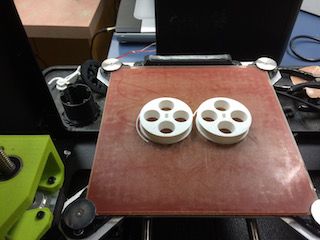
2 white wheels designed and printed in PLA from TinkerCAD model.
Schematics
You'll see below the schematic diagram for connections to the Arduino Pro Mini. As you can see the bi-colour LEDs are represented as two separate LEDs with a common cathode. I've also added a piezo buzzer to D11, which I do not have attached to my current robot but would make a great addition to the project as we still have one PWM port on D11 available after our build. You'll also see that D4 is available for a future sensor.
One item I have not labelled are the serial output pins. These are connected via wires to the rear of the robot to connect to the FTDI serial to USB adapter.
This is the power schematic. As you can see the H-Bridge is powering the motors directly from the output from the battery pack I/O protection board. The Arduino and sensors are driven after the power is dropped down to 5V through the LM2576HVT.
3D Printed parts
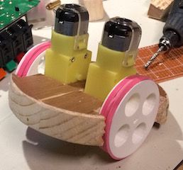
I wasn't happy with the wheels that came with my geared motors. They were far to wide and too big to fit inside the can. Fortunately my work had just purchased a Lulzbot Taz Mini 3D printer. Using Tinkercad I was able whip up these babies in a couple hours. One thing I noticed however is that even though I measured accurately the PLA shrinks when printed so my centre hole is slightly too small. I had to bore them out. To make them grip the floor I used some pink elastics that were around the house. You can download the model file at the bottom of the page .
Construction
1. Chassis Construction:
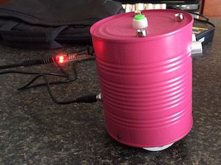
First step was to prepare the tin can. After washing it well I used a Sharpie to measure out where I was to place the LED's, light sensor, on/off button, power jack and serial port. I then used a dremel and my electric drill to drill out the ports. I also spent some time drilling three holes for the wooden base. After this I applied three coats of pink paint to make it a little more feminine.2. Circuit Construction:
Probably most important structurally is the base. I started by tracing a circle with the can onto my piece of wood. I then used a hand saw to cut out a rough circle from the material. To smooth out the jagged edges I used a hacksaw to round it out further and then a file. Finally I finished my circle by sanding the wood down until it fit nicely into the base of the can.
I carefully measured two spaces where the wheels would fit at their diameter, from there I could measure the centre point of each motor. I drew this in pencil on the wood and then cut out those pieces as well with a hack saw. The other piece was the ball bearing which sat too high by default from the base and did not allow the robot to have a slight lean to keep the weight on the back side. I used my dremel with a drill bit and carved down into the wood to create a divot into which I could screw down the ball bearing. To secure the motors I used some quick set epoxy glue. I can't forget I also pre-drilled some holes for the mounting screws and carved a groove into the top of the base where the circuit board will sit. Unfortunately I don't have a picture of that at the moment.
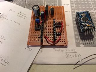
I decided I wanted the arduino to be removable from the chassis. Therefore I chose to put in duPont headers for the Arduino to sit in on the circuit board. The Arduino is sitting in the correct orientation for the board in the picture below. You can see the voltage regulator circuit in the top right of the board and pin headers for all the sensors and LEDs around the periphery of the Arduino headers. On the Arduino itself notice the 6 pins to the south of the board. These are the serial pins that will be connected to the back port of the robot for programming.3. Assembly:
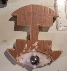
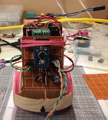
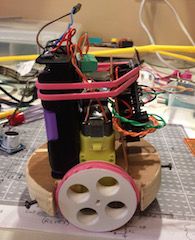
Here are two images from the assembly. From the side profile you can see the sandwich we created. At the back we have the batteries mounted in the black holders (the battery itself is purple). On top of the battery holder is the I/O protection circuit for the lithium-ion batteries. in the middle section we have the two geared motors in yellow with their wires attached to the H-Bridge module which has been glued to the battery pack. From the first assembly picture you should be able to see that the circuit board is held in place by a groove cut into the bottom of the chassis. I've placed scotch tape on the backside of the circuit board to prevent anything from shorting out on the metal motor housing. Finally you can see that the whole assembly is held together by my wonderful rubber band. This works out really nicely actually to keep everything in place.Code
One other note. From here the can goes on top which contains all the wires for the LEDs, power, serial and sensors. When measuring out the length of the cable, be sure to make sure the cable extends about 5cm beyond the bottom of the can. Otherwise you'll have a heck of a time trying to plug everything in. I had to go back in and lengthen a number of connections to make sure I could put the whole shebang together.
Here's the code that I'm currently running. It's rough at the moment and doesn't support the light or voltage sensors. I'll post new code when I have it written The picture below is a shot of the ftdi connected for programming to the back of the bot.
Links#define ledPinA1 2 #define ledPinA2 3 #define ledPinB1 7 #define ledPinB2 8
#define leftFWD 5 #define leftBWD 6 #define rightBWD 9 #define rightFWD 10
#define echoPin 12 #define trigPin 13
//Analog Pins #define lightPin 0 #define voltagePin 1
void setup() { // put your setup code here, to run once: pinMode(ledPinA1,OUTPUT); pinMode(ledPinA2, OUTPUT); pinMode(ledPinB1, OUTPUT); pinMode(ledPinB2, OUTPUT); pinMode(leftBWD, OUTPUT); pinMode(leftFWD, OUTPUT); pinMode(rightFWD, OUTPUT); pinMode(rightBWD, OUTPUT); pinMode(trigPin, OUTPUT); pinMode(echoPin, INPUT);
AllStop(); }
void loop() { long duration, distance; digitalWrite(trigPin, LOW); delayMicroseconds(2); digitalWrite(trigPin, HIGH); delayMicroseconds(10); digitalWrite(trigPin, LOW); duration = pulseIn(echoPin, HIGH); distance = (duration/2) / 29.1;
if (distance < 12) { // This is where the LED On/Off happens AllStop(); LEDBlink(100); LEDBlink(100); LEDBlink(100); LEDBlink(100); analogWrite(leftBWD, 103); analogWrite(rightFWD, 120); delay(400); AllStop(); } else { analogWrite(leftFWD, 103); //This is a value I had to adjust. The robot kept pulling to the right. This slows down the left motor. analogWrite(rightFWD, 120); } }
void LEDBlink(int period) { digitalWrite(ledPinA1, LOW); digitalWrite(ledPinB1, LOW); digitalWrite(ledPinA2, HIGH); digitalWrite(ledPinB2, HIGH); delay(period); digitalWrite(ledPinB2, LOW); digitalWrite(ledPinA1, HIGH); digitalWrite(ledPinB1, HIGH); delay(period); }
void AllStop() { digitalWrite(leftFWD, LOW); digitalWrite(rightFWD, LOW); digitalWrite(leftBWD, LOW); digitalWrite(rightBWD, LOW); }
Arduino: Arduino Pro Mini
Downloads
45mm Wheel with bevel for rubber (STL)
45mm Wheel with bevel for rubber (OBJ)
April 13, 2019
Last Updated: March 8, 2026